Showing posts with label CNC. Show all posts

Thursday, April 21, 2022

What's that over head? Roof, Roof? No...

 It's the ceiling you stupid dog...

Alright, I know - it's one of the worst dad jokes, but that's where we are today.  The ceiling is in, and I'm working on things like wiring, blocking, and poking holes in the side of the trailer (truly an essay in courage, or my lack thereof).

First-up, I added all the blocking on the sides. I made use of the leftover bits of 3/4" ACX to CNC arcs of plywood that matched the arc of the wall.  Hey, once in a while even the blind squirrel gets the nut!  

A couple of pocket holes, a couple of screws, and a little sculpting with the jigsaw, and they were in.  I had intentionally left them a little proud, and once installed, I cleaned them down to the wall line with a pattern bit.

Next up, wiring for all the lights, MaxxFan, and I'm still not sure what else.  Some sort of little command center up front, but I still don't know quite what - so I'll run a bit of flex conduit and a messenger line in it - just in case I figure it out.  With the exception of the 3-way switches for the cabin lights, I'm home running most all of the lights, and using Wago connectors anywhere I have to join two wires.  No wire nuts or crimps to fail.

I'm not particularly proud of these, nor the reason they exist...  In my jumbled planning, I neglected to consider letting in wireways during the build.  As a result, I had to find a way to get wire down to the light switches in the cabin, and surface molding was not a consideration!
So I chose to make a template and hog out a wireway and switch box.  I CNC'd the templates out of MDF (a really bad idea, BTW).  It's really easy to cut MDF, and if you touch it with a router it will make a 1/4" dip.  Since hogging the wireways took a couple of passes, I had a couple of extra opportunities to inflict non-straight lines as I went along.   I also made a second template to cut in a cover plate on the outside so no weak spot in the aluminum right next to the door.

My porch lights are corner mounted, with  a pigtail.  I used a 1 1/2" Forstner bit to cut a pocket in the wall (a little less than 3/4" deep, and then came down from the top with my trusty Kreg pocket bit (it's just about 5 1/4") to provide a dropper.
Same bit chucked up from the inside of the roof, I cut another hole into that top down hole to get the wire to feed thru.

Obviously a little out of sequence, but it looks pretty good up there.


Finally, to fill in the wireways that I hogged out, I 3D printed a set of covers that snuggle in pretty well around the bundle of wires going down the wall.  Printed in 6" sections, and trimmed as necessary.
Yet another excuse to pull out the printer and tell my wife how much I 'saved' by printing my parts!


Wireway covers deployed (well - sort of).  I'll need to move them, trim to fit, and add a little dab of glue, but you get the idea.

Next up - more wiring, wiring the electrical panel, insulating the ceiling and installing the *roof*, and then starting on the dreaded galley hatch and lower front.  

Thursday, March 24, 2022

Update - interior work

If there is one area that I badly underestimated, it's the amount of time that is required to finish the interior.  Varnishing 40 square feet of space is a lot.  Getting it smooth and doing 3 or 4 coats is a whole lot.  And then there's the time spent figuring out that you really didn't think you A/C initial plan through very well, and you will need to do something else.  

I'll do a separate post on the A/C system, but in the short - the return duct will be a 12¨ panel in the headboard, and the cold air will come out of a duct that runs up the middle of the front wall from the top of the headboard.  Not the first change order to hit this project, and I'm sure it won't be the last 

Reddit fans are fond of 'today I learned..." factoids.  Well today I learned that cabinet doors are typically 3/4¨ thick.  So in order to make my Euro hidden hinges work for the headboard, I have to pad the top 3" of the backside of the doors with an extra layer of plywood.  

I'm learning to be a master of multi-tasking.  I generally have 3-4 'tasks' in flight at any given time in the shop, and bounce between them - let the glue dry on 'a', sander is available so work on 'b', finish room is open, so prep 'c' and get it in the finish room, back to 'b' to glue it while 'c' dries.  Grab 30 minutes on CNC when that opens up.  That's pretty much every trip to the shop.  Oh, and the occasional side trip to Menards for brads or whatever.

One other lesson.  While Festool sandpaper is the absolute bomb, I've found that "Serious Grit'' (Amazon) wears almost as well, cuts almost as well, and costs about 50% what Festool paper does.  

This coming weeekend will be devoted to varnish, and maybe, just maybe install all the cross-trailer panels and get the left side stood up!  (more likely early next week, given how much time it takes to varnish...)

One other side note - I *think* all the electrical is in - transfer switch, solar charging, battery system, fuse box, etc.  Now I need to think about lights and switch panels.  Dang this stuff sneaks up on you...


Sunday, March 13, 2022

Weekend Update

 This was supposed to be a post about the first wall was standing and here's the video.  Didn't quite get there for a number of reasons, but I did:

  • Get the right side wall (left has been ready for a week) pocket drilled, grooves cleaned out, and a couple of little annoyances fixed.  Rounded corners cleaned up too!
  • Varnished back wall, ceiling panels
  • Accumulated a little more hardware in prep for final assembly. 

Fridge and stove shelves going together.  It took a little more time and a couple of false starts to get the clearance right so that things fit together properly.  

Hint: 40 thousandths seems about right.  Teeth are 1.98 and notches are 2.02 inches.  

Glued together with Titebond II.  They seem to be plenty strong.  

I got this task out of the way mostly on timing, and to ensure I could size the back partitions correctly. 


Roof spars bundled up to cut wireways.  Yes, I certainly could've done it on the table saw with a sled and a dado blade, but it would take me longer to set that up than it took to draw it in CAD and cut it with CNC.
These started out as an 11' plank of basswood that was pretty straight, dry and pretty good grain structure.  A few passes on the table saw and we have 1 1/4x 2¨ spars.  And I still have a nice bit of basswood in reserve (probably for the hatch!)


The sides came home.   You can see the cladding aluminum standing behind them waiting its turn.  The right side (shown here) will probably get bolted to the floor on Wednesday.


Last but not least, the trailer chassis finally got out of the garage, and the floor got checked for fit.  I always assumed it would fit properly - and it did.  

Sunday, March 6, 2022

Mistakes were made...


The nice thing about CNC is that you can pre-plan you dimensions, create 3D images of the various pieces, model them in place, and *know¨ that what you have drawn will most likely probably fit together flawlessly... 

Until you do something like change the model of cooler you have designed for, andddd... the cooler you bought is 2 inches taller than the one you drew the plan around, and... there was just enough clearance build in for the old one. So a quick trip thru the CNC to make a 3/4¨ slot template, a trip to Rockler for a top bearing 1/2¨ router pattern bit, a little dark stained cherry, and Bob's yer uncle.  One of my shop buddies is fond of saying '' no such thing as a mistake, just an opportunity for an accent feature''  So there's now an ¨accent strip¨ under the counter in back!


Sunday, February 13, 2022

Outer wall laminations

 The outer wall sections are now laminated to the core!  This was kind of a milestone for me - getting the core bonded, and the outers on - Now I can actually visualize the dimensions of the full trailer.  There were a few little gotchas - like the edge at the back of the main outside panel where I was obviously a 1/4"inch closer to y=0 than I thought, and cut the panel just a tad short.  No big deal, but I will need to fill that void where the two outer panels should join up  

I used Titebond III to give myself a bit more work time.  And I learned it takes 16 oz to cover the entire side.  I happened to be in Rockler the other day, and they had this cool 5¨ glue roller that just seemed too good to pass up.  A touch spendy, but boy howdy, it's a lot better than trying to use a 3¨ roller!  The first panel I did I tried making a zigzag pattern with the glue and rolling it out.  Too much work.  Pour on a good puddle and use the roller to spread it out.  Much easier, faster and complete.  Then used a crown stapler to really secure the panels.


I splined the core panels together - 1/4¨ Freud slot cutter on a Bosch 12 Amp router made fast work of it, and a large pile of sawdust to boot.  
I used the ´caul & clamp´ method to pull the panels together, supplemented by bars across the back to keep the panel straight.  And the whole thing was clamped to the bench - again to keep it straight. 

Thankfully the shop has plenty of clamps - long clamps, pipe clamps, pretty much everything but speed clamps.  In a number of spots, I used a clamp across the piece to serve as a holding spot for a longitudinal clamp.  

The next couple of days will be mostly spent doing piddly stuff - making sure my inside wall CNC code is spot on, doing a little finish sanding on the outside in prep for a coat of penetrating epoxy, cutting insulation to fit, and cutting the inside walls.  

Hopefully by next weekend I'm ready to laminate those!

Thursday, February 10, 2022

The Jigsaw puzzle - Part 2

 Tonight's puzzle was brought to you by the letters A, C and X, and the numbers 3 and 4...

I got on the CNC tonight to cut the sidewall cores.  I must be learning something along the way, I didn't make a total hash of it, which is good.  
I don't have a good picture of it, but the CNC manager built an experimental vacuum hold down out of a couple of sheets of 1.5¨ pink foam, hollowed, perforated and glued up.  That and a shop vac makes a perfectly adequate full table clamp. It made aligning the sheet a little tricky, and I did let it slip over a little bit on the last panel - it still worked, but it was a little tight to the edge.  Aside from that, it worked great.

The other little gotcha from this episode is that I learned that the version of FreeCAD I'm using has a bug in the pocket routine.  I was still able to cut the rabbets for shelving and dividers by using a profile command, setting the depth by hand, and making a couple of passes to clear the middle of the groove.  If I'd thought a little longer, I could have offset the cutter by a little more and it would've saved me the clearing pass.

At the end of the day, I wound up with two sidewall cores that will spline together, and they match up with the outer wall.  I left the rear section solid since I haven't finalized the galley build (and may not before I start using it.  As you can see from the rabbets, there is a headboard and two shelves in the cabin, and a 'dead space' that will be the heater on one side, and electrical bay on the other. 


Monday, February 7, 2022

CNC Art


 If you look really closely at the image to the right, you may be able to pick out a few features, or just wonder what in the heck...

This is a composite of the cut jobs for the side wall cores.  The walls are made up of three layers - 1/4" Baltic birch on the outside, 3/4" fir plywood in the middle, and 1/4" Baltic birch on the inside.  Baltic birch is great - better laminations, consistent veneers, no voids.  Fir plywood is, well, plywood.  But it's reasonably solid, straight and inexpensive.  Splurge on the show, cheap on the no-show.

The three cut jobs shown here represent about 10 hours of work on the computer, and will probably take 2 hours of setup/cutting/cleanup.  From some old school boat building I've done, it would probably have taken nearly 40 hours to loft this using an offset table and batten marking, plus another 5-10 hours to cut and then clean up the cuts.  

Now in truth, it's probably a wash to this point.  I've spent an inordinate amount of time learning CAD/CAM, and figuring out some of the 'opportunities for improvement' in FreeCAD.  But the payoff is that now that I *have* figured things out, things like ceiling blocking are a matter of taking a sketch, sectioning a piece of it, and cutting multiple pieces to match.  And since with my design, there's quite a bit of blocking to be done...  That in itself will be a big payoff!

Next up - more CNC fun.  I will try to set up a camera for the whole operation and condense.  Should be interesting.

Thursday, February 3, 2022

The jigsaw puzzle - part 1

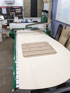
 Pretty good day on the CNC table today.  I didn't break any tools, didn't add any strange lines to the panel or the spoil boards, and didn't run out of table!

I think it actually took longer to clean up than it did to set up and cut.   This was the second outer panel, and it fit nicely with the other parts.  This is the first time I've had all the panels laid out, and they align nicely.  It's taken a bunch of hours to get this set up, and a few little 'learning opportunities to get past, but the payoff when I put this sheet of plywood on the table, anchored it down, and cut it (the video is uncut), was very satisfying!


Monday, January 31, 2022

More CNC fun

We have panels!!!  At the end of the day it all went pretty good - mostly.  I got in the shop tonight, loaded up the first panel, loaded the program, and carved away.  A couple of learnings from tonight.  

1.  Just because the feed chart *says* you can run at 'x' inches/minute doesn't mean you _have_ to run there.  A little slower is an advantage, particularly on smaller tools.  Yep, snapped a mill.

2.  Dealing with warped plywood makes having a partner who can act as a dynamic clamp a real help.  

I'm sure I will have to refine this joint a bit, but for right now - it's zero clearance between the hatch and the back end.


Next up - epoxy on the trailer floor (underside, and maybe some bedliner? (suggestions welcome).  

CNC time

 After more than a little frustration with FreeCAD over the weekend, I was finally able to pin my woes down to a couple of things:  

  1. My drawing had a defect that was not noticeable until you tried to to run the CNC.
  2. FreeCAD didn't handle the Tag dressup very well.  This may be a bug, or yet another artifact of #3 
  3. I still don't know what I'm doing.
The latter is definitely an issue - generally, I suggest people pick something small and simple when learning new technology - like "Hello World".  Not me - I dove in and started with a complex layout that wouldn't fit on a single sheet of plywood, which necessitated splitting up the drawing in ways that are not normally done.  "That's not generally something I'd contemplate" - advice from someone who is supposed to be a CAD guru...

And at the end of the day, I generated sawdust.  You can see the outline on the right - that's the top of the side panel at the rear hatch.  Wait... why does it drop 1" at the end of the curve?? (It shouldn't).  

Fortunately, or irrelevantly, it didn't matter.  Somehow the depth was incorrect, so it only cut the first layer of veneer.  (never commit gcode on a Saturdayy night at 2300 after working on the problem for 12 hours.  I really, really should know better...)

So back to the debug tree, and I *still* don't know why it thinks one of the panels is .4 inches tall, but I learned how to enforce the boundaries, and it's now all on the correct plane - and Yep, I read the gcode itself to verify that!

Off to the shop now to try again.  Hopefully the next post is a set of panels instead of more expensive sawdust!!!


Saturday, January 29, 2022

Weekend update - purchasing and software woes (and successes!)

I spent yesterday afternoon picking up a half dozen Baltic Birch 4x8s from Forest Products.  All good, easy transaction, in and out the door and on my way back home in less than 10 minutes.  I'd planned to spend the evening finishing up the CAD/CAM prep to maybe - just maybe try and CNC a panel this morning.  By 11:00 last night, I'd thrown up my hands in disgust.  I was starting to think that not only was I in over my head, I might be so far down the rabbit hole that the only way out was to back out and start over.  FreeCAD is a wonderful program, but it's got some idiosyncrasies that will drive you to drink.  Look up "Topological Naming Problem" for a glimpse.  There is however, a solution - but it does take pretty much starting fresh.  A branch copy of FreeCAD -that will probably get consumed back into the main product (it's that much better) not only fixes the naming issue, but injects a fair amount of common sense into some of the design elements as well. OK, I could go on for hours about how I stumbled thru the problems, learning the new branch, and watching a metric c___ton of youtube videos to make sense of things I encountered.  Short answer, there was beer involved.

At the end of the day though, I took this:


And turned it into this:
(it's a lot more fun to look at the layout than at the gcode that's really the output)

I greatly underestimated the 'beauty' of turning a 5x10 panel sketch into 4 pieces that could be swiveled around and fit on 3 sheets of plywood.  But it's done now, and tomorrow I'll switch to actually trying to cut the panel on the CNC - or I'll generate sixty bucks worth of sawdust - one of the two, I'm sure!!!
****************************


Friday, December 31, 2021

Making dogbones on CNC

 Here's hoping everyone has a healthy and successful 2022!!! 

Obviously this blog is about my teardrop trailer build, so I won't delve into opinions on beer, people, politics, life, etc - you can catch that over in ¨Life in the swamp¨ if you are interested.  Progress has been kinda slow for the past week.  I have actually had to pull some extra hours at my day job, and that's been enough to occupy most of my time.  In my free time, I've been clearing out the build space, and working on learning how to use the Path workbench in FreeCAD. 

Let's talk a little bit about FreeCAD.  There are other packages that are probably easier to use for generating gcode, like Fusion360 and V-Carve in particular.  Our makerspace/shop has a license for both, and I was starting to learn F-360 when the pandemic hit. At that point, I lost direct access to the machines (makerspace was closed down tight), and the F-360 personal use license was becoming 'difficult'.  Oh, and I built a CAD workstation using Linux, and F-360 only runs under Windows, so - not gonna happen.  Looking at the options, I started investigating FreeCAD, and found it was a)very similar to F-360 in capabilities (and difficulties), b)runs great on Ubuntu Linux, and c)it's really and truly free!  Not a demo license or one that allows you to create but not save, etc.  This is really free, is moderately well documented (good, not great) and has a very active user community, and numerous Youtube communities.

FreeCAD is a 3 dimensional parametric modeling application, with multiple workbenches supporting things like architecture, sheet metal, metal tubing, and 3D printing/CAM/CNC.  

OK, now the bad news.  It's a pain in the ass to learn, crashes occasionally, and many of the videos make assumptions about your existing skills that may or may not be appropriate.  And, while the documentation is often marginal.  If your last drafting experience was paper, ruler, t-square and a compass, it's a complete and total mind warp.  And if you are an 'experiential learner', your brain _will_ hurt - often.  If I paid myself $10/hour for watching FreeCAD youtube videos, I could probably afford a nice windows machine and full pro license for FreeCAD or V Carve!!!

But, I've gotten pretty proficient, made enough 3D widgets and sketches that learning one more bench wasn't that tough.  Even if that one drives a 10K spindle and can destroy 160 bucks worth of plywood in the blink of an eye.  

After a couple of false starts, today was the first day I've cut anything meaningful on the CNC.  It doesn't look like much, but these are the major components of a CNC job - perimeter profiles, grooves and pockets.  The 'dogbone' cutout was the most interesting challenge.  If you work in wood, you've doubtless learned that you can't put a 1/2¨ board in a 1/2¨ rabbet.  It won't fit (without some sanding/chiseling anyway).  Getting a shape like the dogbone to fit is even more of a challenge.  

To make it work, I used a .250 (1/4¨) end mill on the slot, and used the same mill on the tab - but told the program that it was a .240.  This positioned it just a little closer to the edge line, and allowed it to fit very snugly.  I am not sure I could get 10 of these in a row to fit like this though! Nor would the joint contain much glue. For the wall and ceiling seams, I will (after more experimentation) use the same technique, but make it .220 or .230.

And why am I so wrapped up on this particular feature?  Aside from the mechanics of making it work, I think it will be a nice feature on the inner sidewalls of the trailer, and the ceiling.  Having two pieces of plywood simply butt against each other is not the most attractive, and they tend to 'work' against each other over time. You can cover it with trim, or use a scarf joint to make it blend better.  Using puzzle joint means that the two pieces can't move freely, there's more glue seam, and glass tape with epoxy on the back will lock it in for good.  Note: in thicker wood, biscuits, shims or dominos will make a strong mechanical joint.

At the end of the day, I'm a definite fan of FreeCAD, and strongly support the direction that it seems to be going.  It is probably a lot more difficult to work with than a program like SketchUp, but the price is right, and the end result is spot on.  

Hindsight is [almost] always 20/20...

 As I've said before, this trailer has been a very agile project.  There have been more than a few compromises, changes, and adjustments...